[Obsolete. Product is discontinued and is no longer being produced]
|
In many automation applications it is very useful to be able to convert a pulse and direction signal into an incremental encoder signal. This is for instance required in the following cases:
The modules can easily be modified to other conversion functions. Please contact your local JVL representative or JVL A/S directly.
Description:
A pulse and direction signal is converted to an incremental encoder signal with index pulse.
A, B and Z out pulses are 5V balanced. (A+,A-,B+,B-,Z+,Z-)
The pulse and direction inputs are 5V TTL levels.
The index pulse is generated every time 1024, 2048, 4096 or 8192 (selectable) counts have been produced in the internal pulse/direction up/down counter.
The output signal A or B is changed each time a pulse is applied to the pulse input. The frequency of the A or B signal will always be ¼ of the pulse input frequency.
As an extra feature the index pulse (Z output)
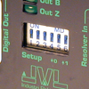
can be inverted at dip-switch 3.
 |
|
|
|
|
|
|
|
|
Also the direction of the output sig-nal can be inversed at dip-switch 4.
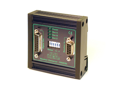
The LED´s "A" and "B" show directly what the level at the output is. The LED "Z" is not representing the actual output level but is toggled every time an index pulse is generated. The index pulse length is the distance between 2 counts.
Example: If the input frequency is 1000Hz, the index pulse will be 1/1000 = 1ms. |


