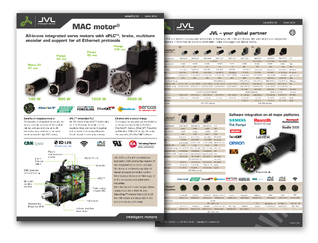
Safe Torque OFF (STO) for MAC140-F , MAC141-F and MAC320-P
The STO Function can be used for disabling the energy to the motor. The motor will thereby be set in a state where it produces no torque.
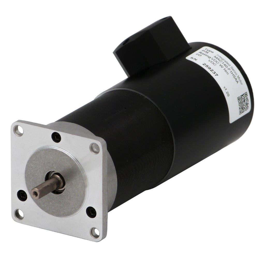
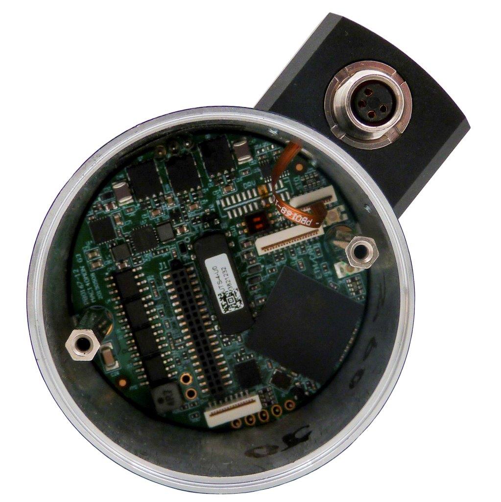
The STO function have its own input connector mounted at the side of the motor.
It is a two input system and it is required that both inputs are activated (applied with a voltage) before the motor is energized and can operate normally.
This STO connector is only available on following products for Servo motors: MAC140-F... and MAC141-F...
Important general information:
- The STO function is not approved by any third party laboratory (only pending)
- Please notice that removing the energy from the motor by use of the STO function do not necessarily stop the motor rotation since any attached load inertia will have an influence when the movement is stopped fully
- The person that install and service the motor must have a general knowledge concerning electrical equipment and safety functions
- The STO function is considered as functional and reliable for 20 years
For Servo Motors 400W and above: MAC400, MAC402, MAC800, MAC1200, MAC1500, MAC3000, MAC4500. Read more about STO here.
For Stepper Motors: MIS17xQ/R/S/T ,MIS23x/Q/R/S/T , MIS34x, MIS43x, MIL23xQ/R/S/T, MIL34x, SMC66 and SMC85. Read more about STO for ServoStep here.
| Partnumber |
| MAC140-F... (Can be delivered with STO connector but not approved by TUV. TUV pending) MAC141-F... (Can be delivered with STO connector but not approved by TUV. TUV pending) |
Ordering information:
MAC motors with the STO function installed are identified by the S option.
| Partnumber | STO connector |
| MAC140-F1GAAA | No |
| MAC140-F1GRAA | Yes |
| MAC141-F1GAAA | No |
| MAC141-F1GRAA | Yes |
| MAC320-P1GRAC | Yes |
How to connect and use the STO function.
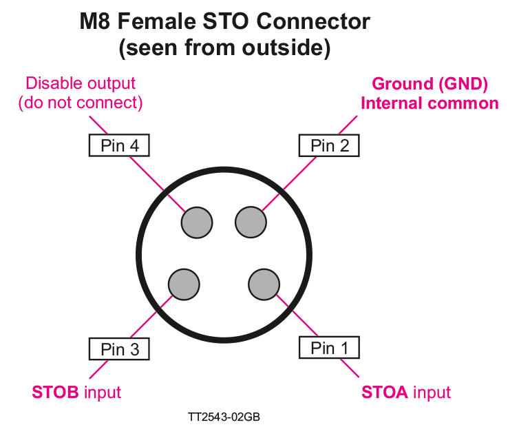
The STO connector contains the two enable inputs STOA and STOB. Both inputs must be applied nominal +24VDC in order to energize the motor and make any motor movement possible.
If only one of the inputs is not applied +24VDC the internal STO circuit will remove the energy from the motor.
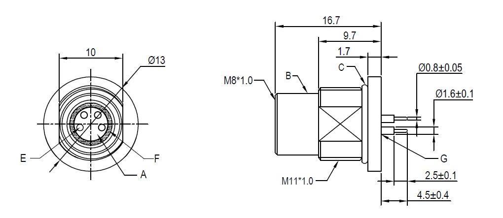
The illustration below shows the pinout of the connector
Accessories:
Disabling the STO function (NON-STO plug)
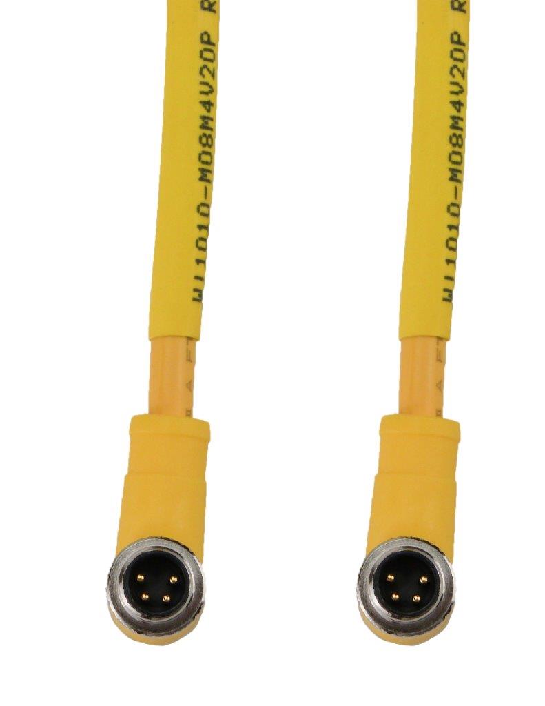
If the STO function is not needed the plug JVL type WI1010-M08M4SSTO must be inserted in the STO connector.
The need of this external plug to disable the STO function is to obtain a high safety level and make sure that no misunderstandings will occur concerning whether the STO function is active or not.
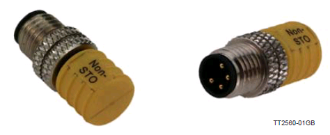
Standard cable
The standard cable is mandatory to use in applications where the TÜV approval is required.
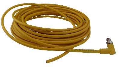
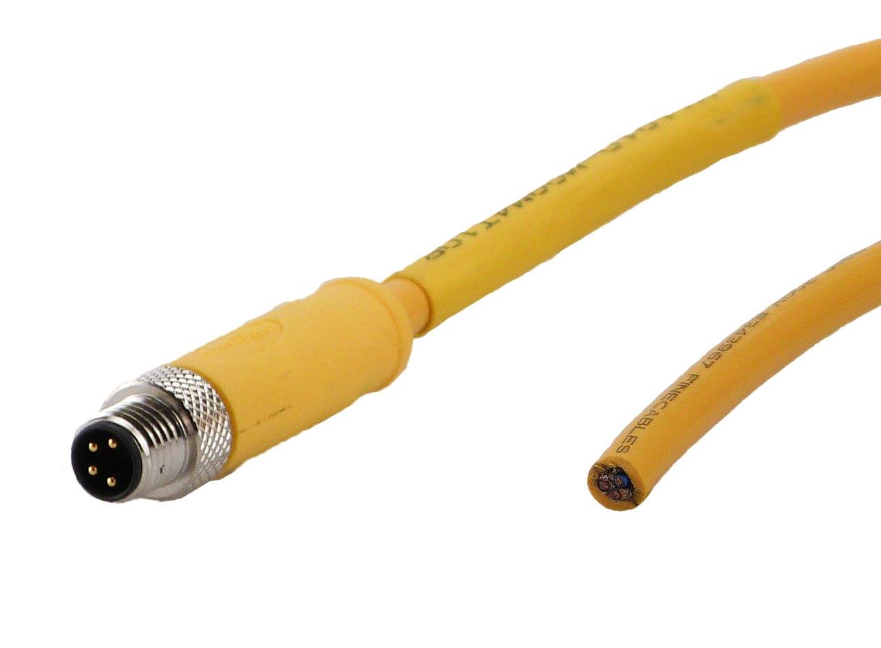
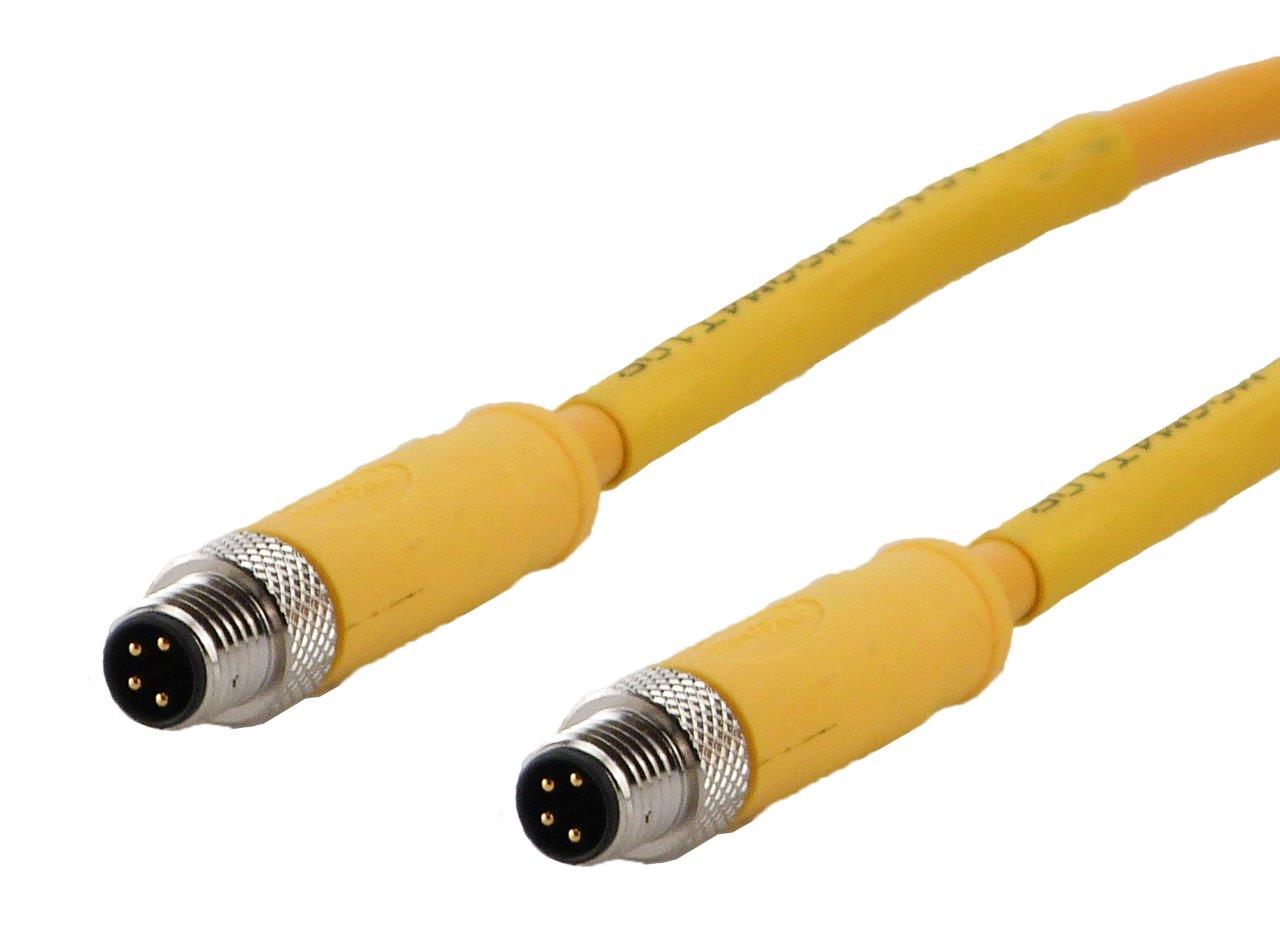
Part number: WI1010-M08M4V05P
How to connect and use the STO function:
The STO connector contains the two enable inputs STOA and STOB. Both inputs must be applied nominal +24 VDC in order to energize the motor and make any motor movement possible.
If only one of the inputs is not applied +24 VDC the internal STO circuit will remove the energy from the motor. Please note: In a SIL3/PLe application, both channels must be controlled simultaneously.
The illustration below shows the pinout of the connector
JVL A/S Bregnerødvej 127 DK-3460 Birkerød Denmark
Tel: +45 4582 4440 Fax: +45 4582 5550 E-mail: jvl@jvl.dk
Tel: +45 4582 4440 Fax: +45 4582 5550 E-mail: jvl@jvl.dk

