

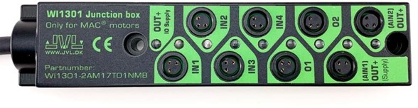
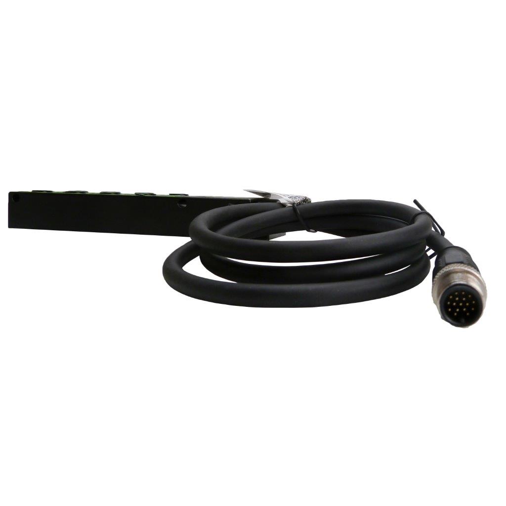
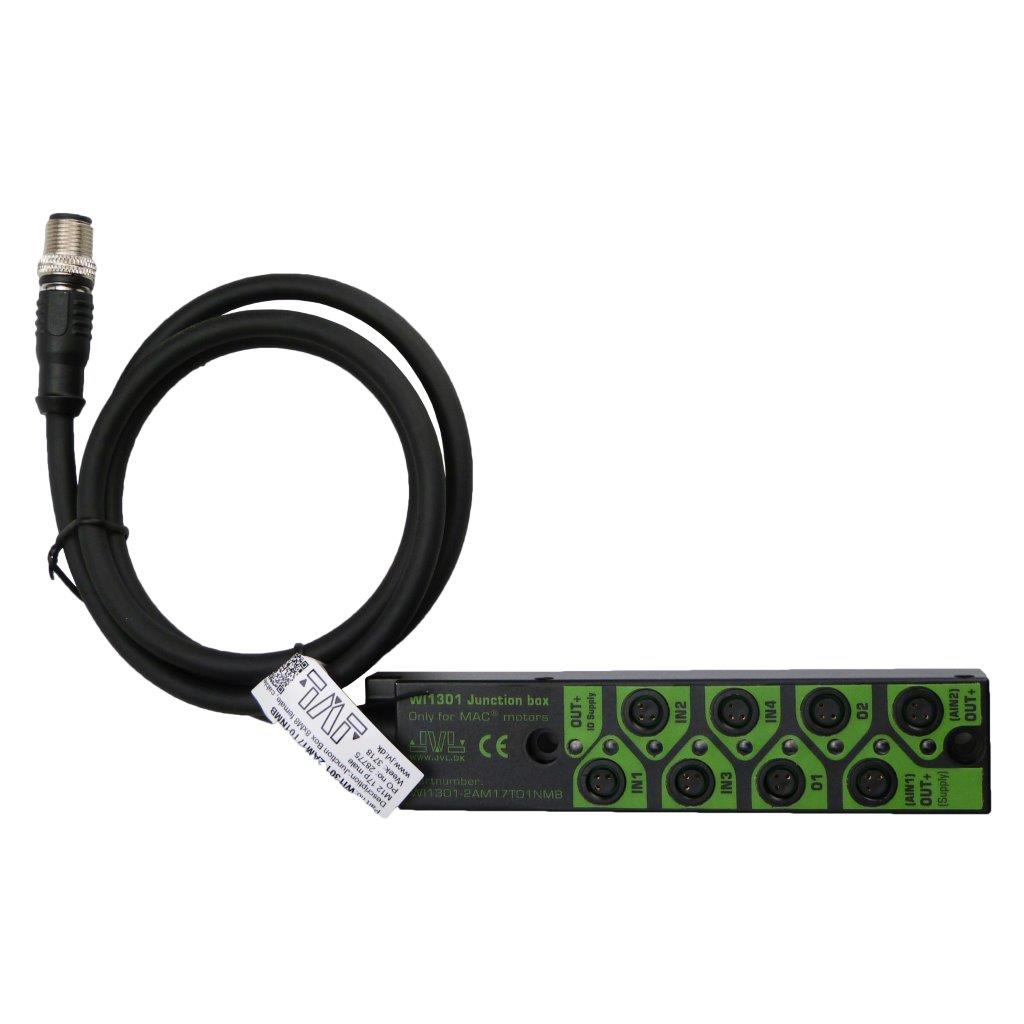
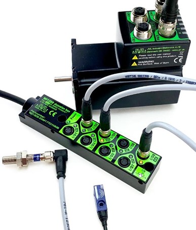
Junction Boxes - WI1301-2AM17T01NMB
|
|
 |
 |
 |
|
||
 |
|||||||
Connections – Ex41 Ethernet module for MAC motor®
 |
Connect sensors and other I/Os according to this diagram, where Female pins are seen from the top of the WI1301. NB! WI1301 can ONLY be used with MAC00-Ex41 modules (not Ex4). |
Supply must be provided in one of two ways:
- Connect external 24 VDC supply using OUT+ (AI2) or OUT+ (AI1). This retains the optic isolation and AI1 and AI2 can't be used anyway because of the isolation.
- Set the DIP switches on the Ex41 module to ON. This method annuls the optic isolation and AI1 and AI2 can be used.
Dimensions

|
DETAILED
|
|
DOWNLOAD
|


JVL A/S Bregnerødvej 127 DK-3460 Birkerød Denmark
Tel: +45 4582 4440 Fax: +45 4582 5550 E-mail: jvl@jvl.dk
Tel: +45 4582 4440 Fax: +45 4582 5550 E-mail: jvl@jvl.dk
